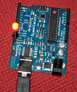
Besides the PICAXE, another popular PIC exists for the electronic hobbyist: the Arduino. Actually, the PICs in use are Atmegas, Arduino is the platform making it easy for people to use the PIC.
The Arduino family consits of a few different boards. I'll be using the Duemilanove, as displayed above, but many more are available for different needs. The Duemilanove has 13 digital input/output pins, 5 analog and an USB connector. Today we'll cover the process of programming an Arduino.
What I like the most about the Arduino platform is that it's all open-source. Except for the PIC that is. The software to program the chip is written in C++ and runs on most platforms. Here is a screenshot:
The proces of programming the Arduino is very simple actually. You write the software and press upload to upload it to the Arduino. The Arduino Duemilanove can be connected to your PC by USB with a USB connector cable.
We are going to built a blink LED, as always ;) The following circuit will show nothing really. It's nothing more than connecting the Arduino to your PC an a LED between digital 13 and the ground. The shopping list for the circuit is:
1 x USB connector cable
1 x Arduino Duemilanove (check Sparkfun.com, it seems to be the cheapest)
1 x red LED
You can open the default Blink example from the file menu (file > examples > digital > blink). Every program has at least a setup function (this code is run as initialization) and a loop function (which is repeated between power up and power down of the board). In the setup function the digital pin 13 is enabled as output. In the loop the output on 13 is set to HIGH, wait for a second, set to LOW and again wait for a second. Nothing really fancy. Upload the program and enjoy the coolness.
maandag 9 november 2009
Abonneren op:
Reacties posten (Atom)


Geen opmerkingen:
Een reactie posten