zaterdag 28 november 2009

Project: Rolling the dice, putting it together

In the previous posts I have talked about building a die, expanding the I/O pins on the Arduino and reading input from a player. Today we are going to build the complete game.

The following circuit is cut in parts. The first circuit  is the overview, the second is one die. Therefore you will need to build the second circuit twice. I've put in transistors, because the PCF8574P will not deliver much current.  The following components are required to build the game:

1 x Arduino Duemilanove
15 x Red LED (7 for each die, 1 for player two)
1 x green LED (player one)
2 x PCF8574P (one for each die)
2 x 1.5 KOhm resistor (brown, green, red, gold) You can use up to 2 KOhm. I put 1 KOhm + 680 Ohm in series instead.
16 x 680 Ohm resistor (blue, gray, brown, gold)

2 x 10 KOhm resistor (brown, black, orange, gold)
14 x transistor (C547B)
2 x press-to-connect buttons


/* define addresses of the dice */
#define DICE_1 (0x4 << 3 | 0x0) // 0100000
#define DICE_2 (0x4 << 3 | 0x1) // 0100001

/* include wire */
#include

/* define pin output for player lights and buttons */
int light1 = 9;
int light2 = 10;
int button1 = 11;
int button2 = 12;

/* define gamemodes */
int gamestart = 0;
int gamePlayer1 =1;
int gamePlayer2 = 2;
int rollingPlayer1 = 3;
int rollingPlayer2 = 4;
int gameEnd = 5;
int gameMode = gamestart;

/* current number for each die*/
int curNum[2];

/* results for each throw */
int result1[2];
int result2[2];

int tick=0;
int tmp=0;
bool tmpBool;
int input;

/* different dicemodes */
byte dicemode[8] =
{
  B0000000,
  B0001000,
  B1000001,
  B1001001,
  B1010101,
  B1011101,
  B1110111,
  B1111111

};

byte curmode_d1;
byte curmode_d2;

void setup()
{
  /* start the I2c */
  Wire.begin();

  /* set pins */
  pinMode(light1, OUTPUT);
  pinMode(light2, OUTPUT);
  pinMode(button1, INPUT);    
  pinMode(button2, INPUT);    
 
  /* reset dice */
  setDiceMode(DICE_1,0);
  setDiceMode(DICE_2,0);
}

void setDiceMode(byte dice, int num)
{
  /* copy a dice mode into the current mode for a dice */
  if (dice == DICE_1)
    memcpy(&curmode_d1,&dicemode[num],sizeof(curmode_d1));
  else
    memcpy(&curmode_d2,&dicemode[num],sizeof(curmode_d2));
}

void showDice()
{
  /* show die one by sending the current mode */
  Wire.beginTransmission(DICE_1);
  Wire.send(curmode_d1);
  Wire.endTransmission();
 
  /* show die two by sending the current mode */
  Wire.beginTransmission(DICE_2);
  Wire.send(curmode_d2);
  Wire.endTransmission();
}

void GameTick()
{
  if (gameMode==gamestart)
  {
    /* game starts, show all lights */
    setDiceMode(DICE_1,7);
    setDiceMode(DICE_2,7);
    showDice();
    digitalWrite(light1, HIGH);   
    digitalWrite(light2, HIGH); 
   
    tmp++;
    if (tmp == 20)
    {
      /* after 2 seconds the game begins, turn all lights off */
      gameMode=gamePlayer1;
      setDiceMode(DICE_1,0);
      setDiceMode(DICE_2,0);    
      showDice();
      digitalWrite(light1, LOW);   
      digitalWrite(light2, LOW);  
      tmp =0;
    }
  }
  else if (gameMode==gamePlayer1)
  {
    /* player one is at turn, blink players one's light */
     tmpBool=!tmpBool;
     if (tmpBool)
       digitalWrite(light1, HIGH);
      else
        digitalWrite(light1, LOW);  
       
     /* did player press his button? */
     input = digitalRead(button1);
     if (input ==HIGH)
     {
        gameMode = rollingPlayer1;
        digitalWrite(light1, HIGH);
        tmp=0;
     } 
  }
  else if (gameMode==gamePlayer2)
  {
     /* player two is at turn, blink players two's light */
     tmpBool=!tmpBool;
     if (tmpBool)
       digitalWrite(light2, HIGH);
      else
        digitalWrite(light2, LOW);  
       
     /* did player press his button? */
     input = digitalRead(button2);
     if (input ==HIGH)
     {
        gameMode = rollingPlayer2;
        digitalWrite(light2, HIGH);
        tmp=0;
     } 
  }
  else if (gameMode==rollingPlayer1)
  {
    /* rolling dice for player 1 */
    tmp++;
    if(tmp < 15)
    {
      /* rolling... */
      curNum[0] = random(1,6);
      curNum[1] = random(1,6);
      setDiceMode(DICE_1,curNum[0]);
      setDiceMode(DICE_2,curNum[1]);   
      showDice();
    }
    /* after 1.5 seconds show result, till 2 seconds passed */
    if(tmp == 20)
    {
     
      memcpy(&result1,&curNum,sizeof(result1));
     
      setDiceMode(DICE_1,0);
      setDiceMode(DICE_2,0);  
      showDice();
      gameMode=gamePlayer2;
      digitalWrite(light1, LOW);  
    }
  }  
  else if (gameMode==rollingPlayer2)
  {
     /* rolling dice for player two */
    tmp++;
    if(tmp < 15)
    {
      /* rolling... */
      curNum[0] = random(1,6);
      curNum[1] = random(1,6);
      setDiceMode(DICE_1,curNum[0]);
      setDiceMode(DICE_2,curNum[1]);   
       showDice();
    }
    /* after 1.5 seconds show result, till 2 seconds passed */
    if(tmp == 20)
    {
      memcpy(&result2,&curNum,sizeof(result2));
      setDiceMode(DICE_1,0);
      setDiceMode(DICE_2,0);  
      showDice();
      gameMode=gameEnd;
      digitalWrite(light2, LOW);  
    }       
  }
   else if (gameMode==gameEnd)
  {
    tmpBool=!tmpBool;
   
    /* was the result for player one more or equal to player two? */
    if (result1[0] + result1[1]>=result2[0] + result2[1])
    {
      setDiceMode(DICE_1,result1[0]);
      setDiceMode(DICE_2,result1[1]);
   
      /* blink LED */ 
       if (tmpBool)
         digitalWrite(light1, HIGH);
        else
          digitalWrite(light1, LOW); 
    }
   
    /* was the result for player two more or equal to player one? */
    if (result1[0] + result1[1]<=result2[0] + result2[1])
    {
      setDiceMode(DICE_1,result2[0]);
      setDiceMode(DICE_2,result2[1]);  
     
      /* blink LED */ 
      if (tmpBool)
         digitalWrite(light2, HIGH);
       else
          digitalWrite(light2, LOW); 
    }
   
    /* blink dice */ 
    if (!tmpBool)
    {
      setDiceMode(DICE_1,0);
      setDiceMode(DICE_2,0);   
    }
   
    showDice();
   
    /* did any player press a button? */
    if ((digitalRead(button1) == HIGH) ||
      (digitalRead(button2) == HIGH))
    {
      /* reset game */
      setDiceMode(DICE_1,0);
      setDiceMode(DICE_2,0);  
   
      showDice();
      digitalWrite(light1, LOW);
      digitalWrite(light2, LOW); 
      gameMode = gamestart;
      tmp=0;
    }
  }
}

void loop()
{
 
  /* ready for antoher tick? */
  if (tick==0)
  {
    GameTick();
  }

  /* tick,tick,tick */
  tick++;
  if (tick==100)
    tick =0;
   
  /* wait a bit */
  delay(1);
}


woensdag 25 november 2009

Project: Rolling the dice, expanding the Arduino (PCF8574P)

Last time we looked at I2C to support communication with other ICs from our Arduino. As I2C is only a communication method, we need an IC to expand the number of I/O pins  available to us, which communicates on I2C. The PCF8574P will just do that for us. Today we are going to blink a LED on distance with our Arduino.

The pin layout for the PCF8574P is as follows:


SYMBOL PIN                               DESCRIPTION
A0         1  address input 0
A1         2  address input 1
A2         3  address input 2
P0         4  quasi-bidirectional I/O 0
P1         5  quasi-bidirectional I/O 1
P2         6  quasi-bidirectional I/O 2
P3         7  quasi-bidirectional I/O 3
VSS       8  supply ground
P4         9  quasi-bidirectional I/O 4
P5        10  quasi-bidirectional I/O 5
P6        11  quasi-bidirectional I/O 6
P7        12  quasi-bidirectional I/O 7
INT       13  interrupt output (active LOW)
SCL       14  serial clock line
SDA       15  serial data line
VDD       16  supply voltage

As we have learned, each slave IC communicating with I2C needs an address. The address is one byte long, but we have only seven bits to send as the eighth bit is an read/write indication. For the PCF8574P the address always starts with 0100, leaving us 3 bits to set. This allows us to have 8 PCF8574P slaves connected in one I2C network, because the bits 1,1,1 = 7. So we have 0 - 7 = 8 possible settings. The three bits are set by connecting the pins a0 - a2 on either Vcc (1) or ground (0). For example if I have set  A0 = 1, A1=0, A2=0 my address to control the PCF8574P  would be: 0100001.

P0 through P7 are the input/output pins much like the ones on the Arduino. VSS is the ground connection pin, while Vdd connects to the voltage supply. INT allows you to disable the PCF8574P by placing a HIGH voltage on the pin. SCL and SDA are the familiar I2C pins which should connect to the Arduino.

The following circuit will  require the following components:
1 x Arduino Duemilanove
1 x Red LED
1 x PCF8574P
1 x 680 Ohm resistor (blue, gray, brown, gold)
2 x 1.5 KOhm resistor (brown, green, red, gold) You can use up to 2 KOhm. I put 1 KOhm + 680 Ohm in series instead.


Note the two resistor connected to the 5 volt pin on the Arduino.The following code will blink the LED:

#define CARD_ADR (0x4 << 3 | 0x0) // address 0100000

/* Include the wire header */
#include

void setup ()
{
  /* setup mwiring */
  Wire.begin();
}

void loop ()
{
  /* set all pins off */
  Wire.beginTransmission(CARD_ADR);
  Wire.send(B00000000);
  Wire.endTransmission();
  delay(1000);
 
  /* set all pins on */
  Wire.beginTransmission(CARD_ADR);
  Wire.send(B11111111);
  Wire.endTransmission();
  delay(1000);  
}


That's it for today, next time we will be completing the project!

maandag 23 november 2009

Project: Rolling the dice, I2C communication

Last time we build the complete game for our project. Although not fully complete, because it was missing a die. We acknowledged that the Arduino didn't have enough digital pins for our needs. Today I am going to explain the I2C communication, next time we will build a circuit expanding the Arduino.

So let's take a look at the possibilities of the Arduino to communicate with other ICs:
- You can communicate using digital pins. You'll have to write code to HIGH/LOW them according to the protocol. This will take a long time and a lot of useful digital pins.
- Of course we have Serial/USB, enabling the Arduino to communicate with your PC or other arduinos. Not really easy and won't allow sketch uploads to your Arduino until you reset.
- Dallas one-wired interface allows you to communicate with other ICs that support it. Will require a digital pin.
- I2C is more common, and the Arduino supports it nicely.

So how does I2C work? The protocol requires a master IC and one or more slaves. I2C has two wires required for communication: a data and a clock.  The master will provide the clock (required for the other IC's to be able to tell when to read the data pin). Both wires should be hooked up with the volt supply with a 4.7 KOhm resistor. This is because when not sending data the line should be HIGH. When an IC decides to send data, it will pull down the data line to LOW (0) or leave it at HIGH (1) for one clock cycle. Each slave will have an address on which it will listen for data.


The Arduino allows you to hook up many devices with I2C and can operate in master or slave mode using the supplied wire.h addition. Using analog pin 4 and 5 to hook up the Arduino, it will allow you to use all the 13 digital pins for other use.

By calling
 
Wire.begin();
in the setup function you can start using I2C.

When you need to send data call to start transmission
Wire.beginTransmission(address);
send data using

Wire.send (data)
and end the transmission with


Wire.endTransmission();
.  What data you need to send depends on what the other IC is expecting. I2C only defines the protocol to send data. You can also read data from other devices with the Arduino, but how depends also on what th slave device is expecting.

So that's the theory. Please check next time on how to put it into practice.

zaterdag 21 november 2009

Project: Rolling the dice, reading input

Part of our game will be pressing a button to role the dice. Last time we build a die. Today we will see how to read input from a player to role the die and play the game.

 Because we have two players, we will need two buttons. A button input is digital, it's either pressed or not. This means we can use it on our Arduino as digital input. The Arduino has 13 digital I/O pins, each configurable as either input or output.

The following circuit will require the following items:
8 x Red LED (1 LED for player two)
1 x Green LED (player one)
1 x Arduino Duemilanove
1 x 680 Ohm Resistor (blue, gray, brown, gold)
2 x 10 KOhm resistor (brown, black, orange, gold)
2 x press-to-connect buttons


The 10 Kohm resistors are required to avoid the Arduino to misread the input pin when the button is unpressed. If not connected with an resistor, the Arduino will randomly see the button as pressed.

The following code will enable us to play the game with one die:


/* translate pin numbers into something human readable */
int dicePinstart =2;
int light1 = 9;
int light2 = 10;
int button1 = 11;
int button2 = 12;

/* game modes */
int gamestart = 0;
int gamePlayer1 =1;
int gamePlayer2 = 2;
int rollingPlayer1 = 3;
int rollingPlayer2 = 4;
int gameEnd = 5;
int gameMode = gamestart;
int curNum;
int result1;
int result2;

/* keep track of the gameticks */
int tick=0;
int tmp=0;
bool tmpBool;
int input;

/* different modes for the die */
int dicemode[8][7] =
{
  {0,0,0,0,0,0,0}
  ,{0,0,0,1,0,0,0}
  ,{1,0,0,0,0,0,1}
  ,{1,0,0,1,0,0,1}
  ,{1,0,1,0,1,0,1}
  ,{1,0,1,1,1,0,1}
  ,{1,1,1,0,1,1,1}
  ,{1,1,1,1,1,1,1}

};

int curmode[8];

void setup()
{
  /* define die LEDs as output */
  for (int i = 0; i<10; i++)
    pinMode(dicePinstart+i, OUTPUT);

  /* define player LEDs as output */ 
  pinMode(light1, OUTPUT);
  pinMode(light2, OUTPUT);
 
  /* define player buttons as input */
  pinMode(button1, INPUT);    
  pinMode(button2, INPUT);    
 
  /* reset the die to no die mode 0 */
  setDiceMode(0);
}

void setDiceMode(int num)
{
  /* copy a die mode into the current diemode */
  memcpy(curmode,&dicemode[num],sizeof(curmode));
}

void showDice()
{
  /* base on the value for the LED in the current die mode, either enable or diable the LED */
  for (int i = 0; i<7; i++)
    if (curmode[i]==1)
      digitalWrite(dicePinstart+i, HIGH);     
    else
      digitalWrite(dicePinstart+i, LOW);    
   
}

void GameTick()
{
  /* this funcction will handle game modes*/
 
  if (gameMode==gamestart)
  {
    /* a new game starts, enable all LEDs to test them */
    setDiceMode(7);
    showDice();
    digitalWrite(light1, HIGH);   
    digitalWrite(light2, HIGH); 
   
    /* count till 20 (2 seconds) */
    tmp++;
    if (tmp == 20)
    {
      /* switch to another gamemode and disable all LEDs*/
      gameMode=gamePlayer1;
      setDiceMode(0);
    
      showDice();
      digitalWrite(light1, LOW);   
      digitalWrite(light2, LOW);  
      tmp =0;
    }
  }
  else if (gameMode==gamePlayer1)
  {
    /* we want the player LED to blink */
     tmpBool=!tmpBool;
     if (tmpBool)
       digitalWrite(light1, HIGH);
      else
        digitalWrite(light1, LOW);  
       
     /* does the player press his button? */
     input = digitalRead(button1);
     if (input ==HIGH)
     {
        /* yes he did, role the die */
        gameMode = rollingPlayer1;
        digitalWrite(light1, HIGH);
        tmp=0;
     } 
  }
  else if (gameMode==gamePlayer2)
  {
    /* we want the player LED to blink */
     tmpBool=!tmpBool;
     if (tmpBool)
       digitalWrite(light2, HIGH);
      else
        digitalWrite(light2, LOW);  
    
     /* does the player press his button? */
     input = digitalRead(button2);
     if (input ==HIGH)
     {
        /* yes he did, role the die */
        gameMode = rollingPlayer2;
        digitalWrite(light2, HIGH);
        tmp=0;
     } 
  }
  else if (gameMode==rollingPlayer1)
  {
    /* role for 1.5 seconds, show the results for 0.5 seconds and continue */
    tmp++;
    if(tmp < 15)
    {
      /* choose a random number */
      curNum = random(1,6);
      setDiceMode(curNum);
      showDice();
    }
    if(tmp == 20)
    {
      /* 2.0 seconds are up, the other player is at turn. reset die and player LED */
      result1 = curNum;
      setDiceMode(0);
      showDice();
      gameMode=gamePlayer2;
      digitalWrite(light1, LOW);  
    }
  }  
    else if (gameMode==rollingPlayer2)
  {
    /* role for 1.5 seconds, show the results for 0.5 seconds and continue */
    tmp++;
    if(tmp < 15)
    {
      /* choose a random number */
      curNum = random(1,6);
      setDiceMode(curNum);
      showDice();
    }
    if(tmp == 20)
    { 
      /* 2.0 seconds are up, the game ends. reset die and player LED */
      result2= curNum;
      setDiceMode(0);
      showDice();
      gameMode=gameEnd;
      digitalWrite(light2, LOW);  
    }       
  }
   else if (gameMode==gameEnd)
  {
     /* we want the result to blink */
    tmpBool=!tmpBool;
   
    /* did player one win, or played a tie? */
    if (result1>=result2)
    {
      /* blink his LED */
      setDiceMode(result1);
      if (tmpBool)
        digitalWrite(light1, HIGH);
      else
        digitalWrite(light1, LOW); 
    }
   
    /* did player two win, or played a tie? */
    if (result1<=result2)
    {
      /* blink his LED */
      setDiceMode(result2);
      if (tmpBool)
        digitalWrite(light2, HIGH);
      else
        digitalWrite(light2, LOW); 
    }
   
    /* blink the die */
    if (!tmpBool)
      setDiceMode(0);
    showDice();
   
    /* did either player pressed his button? */
    if ((digitalRead(button1) == HIGH) ||
        (digitalRead(button2) == HIGH))
    {
      /* reset game */
      setDiceMode(0);
   
      showDice();
      digitalWrite(light1, LOW);
      digitalWrite(light2, LOW); 
      gameMode = gamestart;
      tmp=0;
    }
  }
}

void loop()
{

  /* ready for antohter game tick? */
  if (tick==0)
  {
    GameTick();
  }
 
  /* tick, tick, tick */
  tick++;
  if (tick==100)
    tick =0;
   
  /* wait a bit */
  delay(1);
}


Well that's about it. We are able to play the game... with one die. But we do need two dice. The solution would be simple to connect another 7 LEDs with the Arduino, if the Arduino had another 7 pins left. So we need to extend the Arduino. How? See you later ;)

woensdag 18 november 2009

Project: rolling the dice, building a die

Part one of dice project is to show the pips of a die with LEDs. To do this we require seven LEDs. With these LED we can show every side of the die by light the correct LEDs. But we do need a way to do this. Luckily with the Arduino we have 13 digital pins which we can enable/disable as we please.

The following circuit will show the LEDs and the Arduino to make the die. You will need the following components:

7 x Red LED
1 x Arduino Duemilanove
1 x 680 Ohm Resistor (blue, gray, brown, gold)


The following code will show all sides of the dice:


/* first pin connected to a LED */
int dicePinstart =2;

/* the different states for each LED for each side of the die  */
int dicemode[8][7] =
{
  {0,0,0,0,0,0,0}
  ,{0,0,0,1,0,0,0}
  ,{1,0,0,0,0,0,1}
  ,{1,0,0,1,0,0,1}
  ,{1,0,1,0,1,0,1}
  ,{1,0,1,1,1,0,1}
  ,{1,1,1,0,1,1,1}
  ,{1,1,1,1,1,1,1}

};

/* current side of the die to show */
int curmode[8];

void setup()
{
  /* set all connected pins as output */
  for (int i = 0; i<10; i++)
    pinMode(dicePinstart+i, OUTPUT);    
  
  /* initialize the die as 0 */
  setDiceMode(0);
}

void setDiceMode(int num)
{
  /* copy a side of the die to the current die buffer */
  memcpy(curmode,&dicemode[num],sizeof(curmode));
}

void showDice()
{
  /* for each LED check if it should be enabled for the current die side */
  for (int i = 0; i<7; i++)
    if (curmode[i]==1)
      digitalWrite(dicePinstart+i, HIGH);    
    else
      digitalWrite(dicePinstart+i, LOW);    
}


void loop()
{
  /* loop through the sides of the die */
  for (int i = 0; i <8; i++)
  {
    /* set current side of the die */
    setDiceMode(i);
   
    /*enable the LEDs */
    showDice();
    delay(1000);
  }
}


zondag 15 november 2009

Project: rolling the dice

Time for a new project. This time we are going to build a simple game: Rolling the dice. The game works as follows:

1. Player one presses a button, the dice will role
2. The result of the throw is shown.
3. Player two presses a button, the dice will role
4. The result of the throw is shown.
5. The player with the highest amount of pips wins
6. When any button is pressed, the game resets.

To indicate the player it's his turn, a LED will blink near his button. A throw will show random numbers on the dice for a while, which pauses after a second showing the result. When a player wins, the winning result and his LED will blink. When the game ends in a tie, both players win.

During this project we will learn about communicating with others IC's using I2C. We will learn how to expand the number of I/O pins on the Arduino. Also we be able to read buttons and build dice.

vrijdag 13 november 2009

Circuit basics: Replacement resistance


We have already learned about resistance in circuits. A nice feature of resistance is that you can avoid having many resistors for LEDs in parallel. This can be done by replacing them by one resistor with another resistance. This resistance can be caculated like:

1/Rreplacement = 1/R1 + 1/R2 + 1/RN.

For example, replace 2x680 Ohm resistors:

1/680 + 1/680 = 0.0029
1/0.009 = 340 Ohm.

Or replace 3 resistors:

1/680 + 1/680 + 1/680 = 0.004
1/0.004 = 226 Ohm.

The following circuit proves this:


woensdag 11 november 2009

Electronic component: The Seven-segment display

A personal favorite this time, the seven-segment display. It's pretty cool to see output this way. Later on I will blog about the four digit brother, but today we will build a counter using the Arduino and a seven-segment display.


The seven-segment display consists of 8 segments, also counting the dot. Each segment is an individual LED. The type I used has two vcc pins, this middle ones, and 1 pin for each segment.

To show the digits we are going to build the following circuit. Note that you might have a seven-segment display which has a gnd pin instead of a vcc pin. This way you won't need the transistors as I need did.

The shopping list is as follows:
1 x Arduino Duemilanove
1 x seven-segment display (vcc in)
7 x 10 kOhm resisitor (brown, black, orange)
7 x transistor (C547B)
1 x 150 Ohm resistor (brown, green, brown)
1 x USB connector cable


Using the 5 Volt and ground pin on the Arduino board, we can power the circuit. The pins dig7 - dig 13 are connected to the transistors. By enabling a pin a current will flow through the corresponding segment.

Well that's the first part. Up next is programming the Arduino. This is quite annoying, as we'll have to tell the arduino which pins to enable for each digit. While running the Arduino will count till 10, on which it will start over with 0.


/* define the segments */
 int ledPinMid =  13; 
 int ledPinLeftUp =  12;  
 int ledPinUp =  11; 
 int ledPinRightUp =  10;  
 int ledPinLeftDown =  9;
 int ledPinDown =  8; 
 int ledPinRightDown =  7;  
 int i =0;


 void setup()   {               
   // initialize the digital pins as output:
   pinMode(ledPinMid, OUTPUT);    
   pinMode(ledPinLeftUp, OUTPUT);    
   pinMode(ledPinUp, OUTPUT);    
   pinMode(ledPinRightUp, OUTPUT);    
   pinMode(ledPinLeftDown, OUTPUT);    
   pinMode(ledPinDown, OUTPUT);    
   pinMode(ledPinRightDown, OUTPUT);    
 }

 void clear()
 {
   digitalWrite(ledPinMid, LOW);
   digitalWrite(ledPinLeftUp, LOW);
   digitalWrite(ledPinUp, LOW);
   digitalWrite(ledPinRightUp, LOW);
   digitalWrite(ledPinLeftDown, LOW);
   digitalWrite(ledPinDown, LOW);
   digitalWrite(ledPinRightDown, LOW);
 }

 void setNumber(int number)
 {
   /* disable all pins */
   clear();
  
   /* enable the pins for the current number */
   switch (number)
   {
     case 1:
     digitalWrite(ledPinRightUp, HIGH);
     digitalWrite(ledPinRightDown, HIGH);
     break;
     case 2:
     digitalWrite(ledPinUp, HIGH);
     digitalWrite(ledPinRightUp, HIGH);
     digitalWrite(ledPinMid, HIGH);
     digitalWrite(ledPinLeftDown, HIGH);
     digitalWrite(ledPinDown, HIGH);
     break;
     case 3:
     digitalWrite(ledPinUp, HIGH);
     digitalWrite(ledPinRightUp, HIGH);
     digitalWrite(ledPinMid, HIGH);
     digitalWrite(ledPinRightDown, HIGH);
     digitalWrite(ledPinDown, HIGH);
     break;
     case 4:
     digitalWrite(ledPinLeftUp, HIGH);
     digitalWrite(ledPinMid, HIGH);
     digitalWrite(ledPinRightUp, HIGH);
     digitalWrite(ledPinRightDown, HIGH);
     break;
     case 5:
     digitalWrite(ledPinUp, HIGH);
     digitalWrite(ledPinLeftUp, HIGH);
     digitalWrite(ledPinMid, HIGH);
     digitalWrite(ledPinRightDown, HIGH);
     digitalWrite(ledPinDown, HIGH);
     break;
     case 6:
     digitalWrite(ledPinUp, HIGH);
     digitalWrite(ledPinLeftUp, HIGH);
     digitalWrite(ledPinMid, HIGH);
     digitalWrite(ledPinRightDown, HIGH);
     digitalWrite(ledPinLeftDown, HIGH);
     digitalWrite(ledPinDown, HIGH);
     break;
     case 7:
     digitalWrite(ledPinUp, HIGH);
     digitalWrite(ledPinRightUp, HIGH);
     digitalWrite(ledPinRightDown, HIGH);
     break;
     case 8:
     digitalWrite(ledPinUp, HIGH);
     digitalWrite(ledPinLeftUp, HIGH);
     digitalWrite(ledPinRightUp, HIGH);
     digitalWrite(ledPinMid, HIGH);
     digitalWrite(ledPinRightDown, HIGH);
     digitalWrite(ledPinLeftDown, HIGH);
     digitalWrite(ledPinDown, HIGH);
     break;
     case 9:
     digitalWrite(ledPinUp, HIGH);
     digitalWrite(ledPinLeftUp, HIGH);
     digitalWrite(ledPinRightUp, HIGH);
     digitalWrite(ledPinMid, HIGH);
     digitalWrite(ledPinRightDown, HIGH);
     digitalWrite(ledPinDown, HIGH);
     break;
     case 0:
     digitalWrite(ledPinUp, HIGH);
     digitalWrite(ledPinLeftUp, HIGH);
     digitalWrite(ledPinRightUp, HIGH);
     digitalWrite(ledPinRightDown, HIGH);
     digitalWrite(ledPinLeftDown, HIGH);
     digitalWrite(ledPinDown, HIGH);
     break;
   }
 }

 // the loop() method runs over and over again,
 // as long as the Arduino has power

 void loop()                    
 {
     /* set current number */
    setNumber(i);
    i ++;
    if (i == 10) // after 10 second, reset
      i = 0;
    delay(1000); // wait for a second
 }


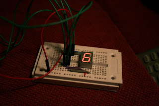
Well that's it for today. Let's take a look at the result.


maandag 9 november 2009

Electronic component: The Arduino board

Besides the PICAXE, another popular PIC exists for the electronic hobbyist: the Arduino. Actually, the PICs in use are Atmegas, Arduino is the platform making it easy for people to use the PIC.


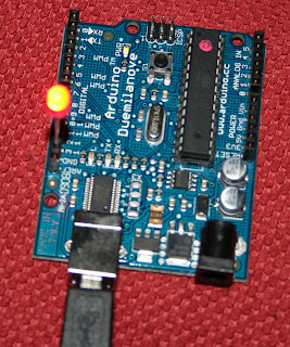
The Arduino family consits of a few different boards. I'll be using the Duemilanove, as displayed above, but many more are available for different needs. The Duemilanove has 13 digital input/output pins, 5 analog and an USB connector. Today we'll cover the process of programming an Arduino.

What I like the most about the Arduino platform is that it's all open-source. Except for the PIC that is. The software to program the chip is written in C++ and runs on most platforms. Here is a screenshot:


The proces of programming the Arduino is very simple actually. You write the software and press upload to upload it to the Arduino. The Arduino Duemilanove can be connected to your PC by USB with a USB connector cable.

We are going to built a blink LED, as always ;) The following circuit will show nothing really. It's nothing more than connecting the Arduino to your PC an a LED between digital 13 and the ground. The shopping list for the circuit is:

1 x USB connector cable
1 x Arduino Duemilanove (check Sparkfun.com, it seems to be the cheapest)
1 x red LED


You can open the default Blink example from the file menu (file > examples > digital > blink). Every program has at least a setup function (this code is run as initialization) and a loop function (which is repeated between power up and power down of the board). In the setup function the digital pin 13 is enabled as output. In the loop the output on 13 is set to HIGH, wait for a second, set to LOW and again wait for a second. Nothing really fancy. Upload the program and enjoy the coolness.


vrijdag 6 november 2009

Project: The light-o-meter

Ok, this is the final chapter in the project. We are going to build the actual meter. In the previous postings we've learned to program the PICAXE and use the LDR. Up next is to combine these into one circuit.

One nice feature of the PICAXE 18X is to be able to read analog components, by connecting them to an input pin. This will have to be either input0 (pin 17) or input1 (pin 18) as they have ADC support.

This is how the meter is going to work. The LDR will be used by the PICAXE to determine the amount of light. Based on the amount of light LEDs will be lit or unlit. The more light, the more LEDs will be lit.

For the following circuit we will require these items:
1 x 9V Battery
1 x LDR
1 x 10 kOhm resistor (brrown, black, orange)
1 x 4.7 kOhm resistor (I still use three)
8 x 1 kOhm resistor (brown, black, red)
8 x  C547B transistor
3 x green LED
3 x yellow LED
2 x red LED


Ok, here we go. Step by step:

1. Place the PICAXE on the board, like the last time.


2. Put the 8 LEDs on the board


3. For each LED, put a resistor between the LED and ground.
 

4. For each LED add a transistor to the board. Whatch carefully how to connect them.
 

5. Connect each transistor to the appropriate pin on the PICAXE. See the pin layout in the previous post for more details.

 
6. Connect an LDR to the + pole, and the 10kOhm resistor. The resistor should be connected to the - pole. Connect input 1 of the PICAXE to the LDR and resistor.

 
7. Review the result before you blow anything up ;)


8. upload the following code into the PICAXE:

main:
readadc 1, b0 'Read the amount of light 0=dark 255=very much

'Is it very bright? put led 7 on
if b0 > 230 then
    high  7
else
    low 7
end if

'Is it less very bright? put led 6 on
if b0 > 200 then
    high  6
else
    low 6
end if

'Is it bright? put led 5 on
if b0 > 180 then
    high  5
else
    low 5
end if

'Is it medium bright? put led 4 on
if b0 > 150 then
    high 4 
else
    low 4
end if

'Is it below medium? put led 3 on
if b0 > 120 then
    high  3
else
    low 3
end if

'Is it between dark and medium bright? put led 2 on
if b0 > 90 then
    high  2
else
    low 2
end if

'Is it less dark? put led 1 on
if b0 > 60 then
    high  1
else
    low 1
end if

'Is it quite dark? put led 0 on
if b0 > 30 then
    high  0
else
    low 0
end if

goto main


This is the result:


woensdag 4 november 2009

Electronic component: The PICAXE

For our project we are going to use a PICAXE, today we are going to learn what the PICAXE is and how to program it. This we will be doing by building a circuit which is sending out an SOS signal in Morse code.

The PIXAXE is a PIC. IC stands for integrated circuit, as we already have learned. PIC stands for programmable integrated circuit. This means that you can write code and upload it onto the chip. Based on input you can set a different output.

For the project I've used an PICAXE 18X, but there are many different types of PICAXE chips. Also different PICs exist, for example the Atmel chips which we will meet later on.

As we are about to program a PIXAXE, we do require some items. I bought them at SparkFun, which seem to be nice guys. For today's circuit, this is what we need:
1 x PICAXE 18X (Some other PICAXEs will be ok too, but you are on your own ;))
1 x PICAXE Serial programmer cable


1 x PICAXE Bread board adapter (instead you might want to get the PICAXE 18 pin power project board, but I found this to be more flexible, although you will have to solder it)


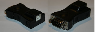
1 x USBtoRS232 converter, as my PC doesn't have a serial port.
 
1 x USB connector cable
 
1 x 9V battery
1 x 4,7 kOhm (I used 2 x 2.2 kOhm + 1 x 330 Ohm in series, as I didn't have one)
1 x green LED

Well, that's about it. Here is the circuit we are going to build:


To imitate the PICAXE Bread board adapter, I've used three signal input symbols. It's pretty straightforward I guess. Note that this is the actual pin layout for the PICAXE 18X:


Ok, once you have connected everything, including the serial and USB cable, we can start programming the PICAXE. As I use Linux I'll be using AXEpad, which is really easy to use. For Windows you will probably have to set up some drivers and download another program. The code for the PICAXE will be the same anyway, so here we go:

main: ' start here
    gosub short ' jump to short
    gosub short ' jump to short
    gosub short ' jump to short
    pause 200 ' wait 200 msec
    gosub long ' jump to long
    gosub long ' jump to long
    gosub long ' jump to long
    pause 200 ' wait 200 msec
    gosub short ' jump to short
    gosub short ' jump to short
    gosub short ' jump to short        
    pause 3000 ' wait 3 sec
    goto main ' jump back to main

short: 
    high 4   ' Set output 4 to ON     

   pause 100 ' wait 100 msec
    low 4   ' Set output 4 to OFF
    pause 100 ' wait 100 msec
    return  ' Jump back to main
     
long:
    high 4  ' Set output 4 to ON
    pause 300 ' wait 300 msec     

    low 4  ' Set output 4 to OFF
    pause 300 ' wait 300 msec
    return  ' Jump back to main


The code is pretty human readable. It looks a bit like BASIC. Just put the code in the editor and upload it the PICAXE. If everything goes OK, you will be seeing a LED that's blinking short-short-shot-long-long-long-short-short-short.

That's it for now. Till next time.

maandag 2 november 2009

Electronic component: Light Dependent Resistor (LDR)

Part of the project is to find out what a LDR is and does. As the name suggests it has something to do with resistance and with light. Depending on the type the resistance will be lower when more (or less) light falls on the LDR. But you can  build the circuit either way.

Today's shopping list contains:
1 x LDR
1 x 10 kOhm Potentiometer
2 x 330 Ohm resistor
1 transistor BC547B
1 x green LED
1 x 9V battery

The following circuit will light a green LED when there is little light. By adjusting the potentiometer you can control the amount of light required.


This works basically because when the LDR recieves a lot of light, the resistance will drop. The current will not go through the transistor. As the amount of light drops, the resistance of the LDR will decrease. After a certain point, the current will prefer the transistor instead of the LDR, enabling the green light.


zaterdag 31 oktober 2009

Project: Building a light meter (1)

This is the first project I have started. Nothing to fancy, but something fun to do. Goal is to build a light meter, which measures the amount of light in the environment. It outputs the amount of light by lighting LEDs. The more light, the more LEDs will be lit. We will measure the amount of light with a LDR component.

The key component will be the PICAXE. This is a programmable IC (PIC) for low-end purposes. During the project we will be learning:

- How to use a LDR component
- How to program a PICAXE
- How to build the light meter


vrijdag 30 oktober 2009

Circuit basics: Resistance (2)

Last time I blogged about resistance. Today we are going to look at resistance within a circuit. Everything has basically to do with Ohm's Law, which states states:

the current through a conductor between two points is directly proportional to the potential difference or voltage across the two points, and inversely proportional to the resistance between them. (http://en.wikipedia.org/wiki/Ohm%27s_law)
This means that you can calculate the current if you know the voltage and the resistance. Also true is that you can calculate the voltage if you know the current and the resistance, and finally the resistance if you know the current and the voltage.

The formula for Ohm's law is: U = I x R, where U is voltage (in Volts), I is current (in Ampere) and R is resistance (in Ohm). You can also write this as I = U / R or R = U / I.

Given the following circuit:


Here we have the three variables:  U = 9 Volts, R= 450 Ohm and I = 0.020 Ampere (0.020 A = 20 mA). Let's check:

I x R = U
0.020 x 450 = 9 Volts


Ok, here are some circuits, which value is the missing variable? Rhe answers are at the bottom.


1. Given: U = 9, I = 0.0257. What is R?


2. Given: R= 350, I = 0.0143. What is U?


3. Given: U = 9, R=650. What is I?


4. How much resistance does the LED generate?


5. This circuit has a current of 23.6 mA. How much Ohm is the resistance of the resistor?


1. 9 / 0.0257 = 350 Ohm
2. 350 x 0.0143 = 5 Volts
3. 9 / 650 = 13.8  mA = 0.014 A
4. 1.9 / 0.0103 =   184 Ohm
5. As we have learned, the sum of the components in series is the total voltage. So  9 - 1.92 = 7.08 V.  7.08 / 0.0236 = 300 Ohm