There are a few types of transistors, but I will use only the C547B. You should be able to find this transistor (or similar) at any electronics shop. Or you might find a few in a electronic device you want to get rid of.
The transistor has three terminals: base (b), collector (c) and the emitter (e). If you put current on the base, a current will flow from collector to emitter.
The following circuits will demonstrate the use of the transistor as a switch. Refer to the list of electronic components in one of my other blog posts for the meaning of the symbols used. The first circuit will light a LED when the button is pressed. The following components are required to build the circuit:
1 x 150 Ohm resistor (brown green brown gold)
1 x 1k Ohm resistor (brown black red gold)
1 x C547B transistor
1 x 3V power supply
1 x Red LED
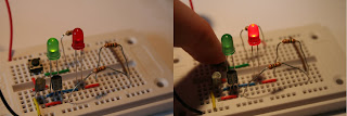
Now as a bonus I will show another example. We'll take the same circuit, but add another LED (green). When the button is up this LED will light up, when the button is down it will go off. The result is that either the red LED is on, when the button is pressed, or the green LED is on. The shopping list for this circuit would be:
2 x 150 Ohm resistor (brown green brown gold)
1 x 1k Ohm resistor (brown black red gold)
2 x C547B transistor
1 x 3V power supply
1 x Red LED
1 x Green LED
I have placed the second transistor in parallel to the first transistor. The green LED is then placed in parallel to the transistor. That way the transistor will work as a NOT logic segment: when no current is placed on the transistor the LED will light up, otherwise it will go off.
Well that's it for today, thanks for reading.


Magnificette - Buy High-Quality Electronic Components Online - Cables, Connectors, ICs & More
BeantwoordenVerwijderen